|
 
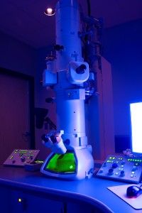
Forensic engineers often use expert tools to help them better scrutinize damaged parts and materials in order to obtain information as to why the breaks or failures occurred. As a simple example, a high resolution camera may be used to take a variety of pictures of a crashed vehicle. The photos can then be expanded somewhat and pictures from different angles can be compared. Although modern digital cameras can capture small items with high resolution, sometimes it helps to see greater detail than a zoom lens will allow. Enter the optical microscope! Just like a camera, the optical microscope still needs visible light (photons) to reflect off of an object in order to be magnified and seen. It is a great tool for visualizing structures that are too small for the unaided eye to see. Optical microscopes can magnify images up to 1000 times, though much lower magnifications are sufficient to visualize a specimen and resolution/focus can become compromised at very high magnifications. This magnification limit is actually a physical limitation imposed by the wavelength of light itself. These microscopes are lightweight, inexpensive, easy to set up and very portable. But what if greater magnification is needed? Enter the electron microscope! This microscope works on a completely different principle than an optical scope.
Optical: 
Apple Damaged Cells
Electron: 
Wasp Head Tongue Bacteria
No visible light is needed here and thus no light wavelength limitation. Although there are different ways an electron microscope can work, they all use negatively charged particles (specifically electron beams) to either be scattered around or transmitted directly at a sample. The electron microscope uses the electrons much like the optical microscope uses light. However, the sample being examined needs to meet certain criteria and/or be specially prepared for the electrons to “see” it and produce images. The biggest advantage an electron microscope has over an optical one is higher resolution – up to around 2 million times the actual size! It is possible to view a three-dimensional external shape of an object or a two-dimensional cross sectional of a thinly prepared sample. Also, Energy-dispersive spectroscopy (EDS) can often be conducted alongside magnification using an electron microscope. EDS is an analytical technique used to get an initial idea of the chemical characterization of a sample (What it is made of).
Trivia Fact: The world’s most powerful microscope currently resides at the University of Victoria, Canada. The seven-ton, 14.7 feet tall Scanning Transmission Electron Holography Microscope (STEHM), can see roughly 20 million times better than the human eye! Of course there are some disadvantages to using an electron microscope. These devices are big, heavy, require training to use and are expensive to manufacture and maintain. The samples have to be completely dry and stationary. As electrons have no color, all images are black & white. However, sometimes color can be added to the image artificially to give a better visual impression. Although objects can be viewed non-invasively using optical microscopes, destruction is usually the end-fate of any object to be studied under an electron microscope. Sample preparation includes not only cutting it down to a small or thin size, but also possibly coating it with a metal (like gold) and then viewing it while inside a vacuum. Without a vacuum, electrons being aimed at the sample would be deflected when they hit air particles.
When a component fails (separates or fractures), it is compromised such that it is no longer in one continuous piece. The fractured surfaces exposed in the failure contain visual information about why they broke apart. Microscopes can be used to examine a plastic pipe to see why it cracked or a metal crank shaft to see why it broke. In fire cause and origin investigations, examining electrical wires and determining whether they or other conductors in the area have a signature of either arcing or melting is a critical part of identifying competent ignition sources.
For the most part, an optical microscope is adequate for examining fractured edges when looking for characterizations of failure mechanisms that could have motivated a separation. Exploring the size and depth of pores found in cast aluminum as well as identifying any potential contaminants would be a job better suited for an electron microscope.
CED engineers will arrive at a site equipped with tools that can be employed immediately at that inspection. Sometimes discoveries made at the site point to the potential existence of additional information. It is here that perhaps the most important tools a CED engineer brings with them to the site is their own training and experience that allows them to recognize when additional resources, equipment or expertise are appropriate.
Submit a case or claim online.
Contact a CED Engineer in your region.
|

